Air leakage at the connection points of an aeration mixer often develops slowly over time, starting with tiny bubbles that are easy to overlook during daily operation. As the gap at the interface expands, the system will lose effective air pressure, reduce dissolved oxygen transfer efficiency, and force the whole unit to run under unnecessary extra load. Many operators notice that the mixer can no longer maintain stable working performance in deep water, even when the main motor and impeller are still in good condition. Targeted inspection and proper repair can seal these leakage points effectively and restore the system to its original airtight state.
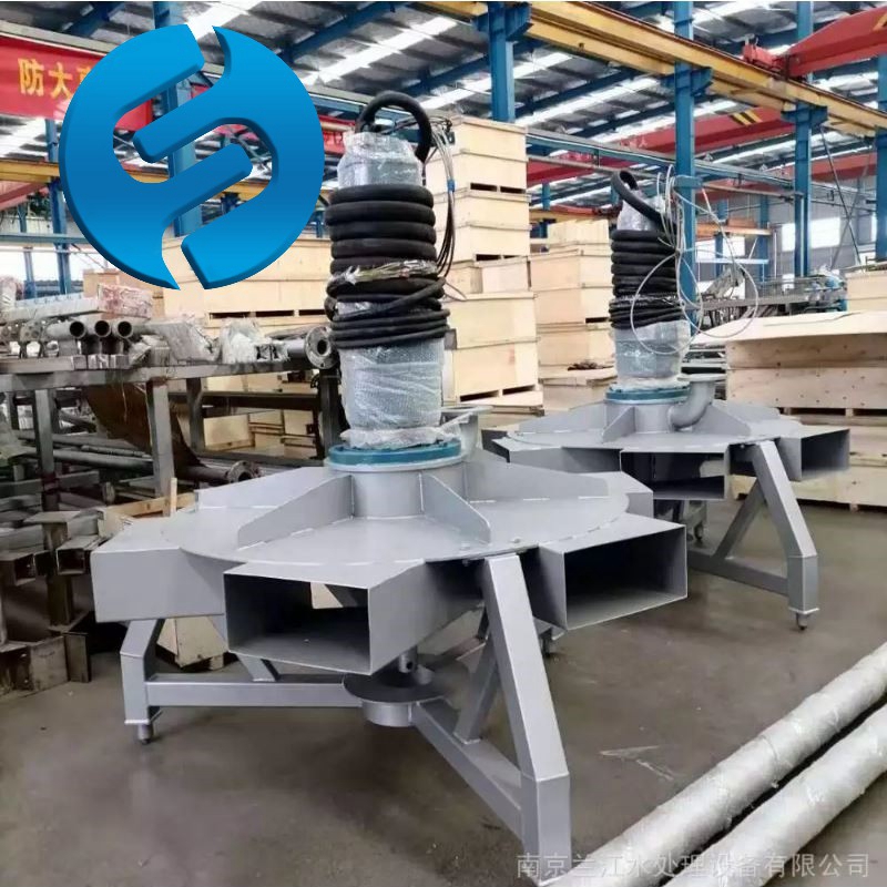
Early detection of hidden interface leakage
Most interface air leaks do not produce obvious loud noise at the initial stage, so they are often mistaken for normal air release from the aeration structure. Operators may observe scattered fine bubbles emerging from the joint area rather than from the designed aeration outlet, or notice that the inlet air pressure reading shows an unexpected drop even when the air supply remains unchanged. Slight pressure fluctuation during continuous operation, abnormal moisture accumulation around the connection flange, and inconsistent dissolved oxygen readings across different sections of the tank are other common early signs of hidden interface leakage.
These subtle signals are easy to ignore during routine patrols. If left unaddressed, the leakage path will gradually expand under the combined effect of water pressure, vibration, and temperature cycling. This will eventually lead to a sharp drop in effective aeration depth and waste a large amount of input power that should have been used for oxygen transfer.
Surface preparation before repair
Before carrying out any repair work, the affected section must be fully isolated from the air supply system and drained completely. Release all residual internal pressure safely, and make sure no trapped air remains inside the pipeline that could cause unexpected pressure release during the operation.
Clean the entire interface area thoroughly to remove all biological fouling, sediment, oil residue, and old residual sealing material. Use non-abrasive methods to treat the mating surfaces, so that no scratches or uneven marks are left on the metal or composite contact faces. Inspect the two connected flanges or joint ends carefully for any deformation, localized corrosion, or tiny cracks that have formed along the sealing line. If the surface flatness no longer meets the original design standard, carry out gentle surface reconditioning to restore uniform contact across the entire joint face.
Sealing structure reconditioning
Once the mating surfaces are fully prepared and confirmed to be in good condition, install new sealing elements that match the operating temperature, water quality, and pressure range of the working environment. Make sure the sealing material is properly positioned and not twisted, stretched, or misaligned during installation.
Tighten the connecting fasteners in a symmetrical sequence, applying even incremental torque across the whole flange rather than tightening one side fully before moving to the next. This method ensures that the sealing pressure is distributed uniformly around the entire interface, preventing local gaps that could create new leakage paths. After preliminary tightening, rotate the connected assembly slightly to check for any uneven stress, and readjust the torque values to eliminate any misalignment that may have been introduced during the process.
On-site leakage verification after repair
Once the repair work is finished, do not put the unit directly back into full operation. Carry out a low-pressure air test first with the outlet end temporarily blocked, and maintain the test pressure at a level slightly higher than normal working pressure for a sustained period.
Observe the entire repaired interface carefully, and use a non-corrosive test method to check for any tiny escaping bubbles. If no leakage is found during the static pressure holding test, gradually restore the system to normal working state and run the aeration mixer under actual operating water depth. Monitor the inlet air pressure, motor current, and bubble distribution around the repaired joint continuously for several hours. Record all new baseline data, and compare it with historical records to confirm that the interface remains completely airtight under real dynamic load and vibration conditions.
Post time:2026-09-14
