Aeration Mixer Impeller Jamming and Seizure Resolution
Implementing Full Lockout and Pre-Inspection Safety Protocols
Before any hands-on inspection or repair work begins, crews follow strict, documented safety procedures to isolate all connected power, air, and hydraulic supply lines. They confirm zero energy state at every connection point, and post clear work zone markers to prevent unintended system activation while technicians are in or around the tank. Teams also test residual current levels and confirm no stored rotational energy remains in the drive assembly before any disassembly work starts. This structured pre-work step eliminates preventable safety risks and creates a stable working environment for accurate fault diagnosis.
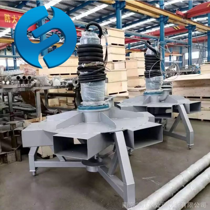
Conducting External and Partial Disassembly Fault Survey
Technicians first perform a full external visual and tactile inspection of the entire unit, checking for abnormal vibration marks, leaking seal fluid, or unusual mounting shifts that can point to the root of the jam. They manually attempt slow, controlled rotation of the impeller shaft in both directions, noting exact points of binding, hard seizure, or partial movement that reveals where friction or obstruction is occurring. Based on these initial observations, they remove only the necessary access panels and protective covers to reach the affected area, avoiding unnecessary full teardown that can introduce extra assembly errors later. This targeted survey narrows down the exact location of the jam without disrupting undamaged system components.
Clearing Trapped Debris and Resolving Mechanical Interference
Fibrous waste, hardened sludge chunks, and stray foreign objects are the most common causes of sudden impeller jams, and technicians carefully extract all trapped material from around the impeller blades and between the rotating and stationary assembly gaps. They inspect every blade edge, hub surface, and surrounding housing wall for scratches, dents, or deformed material that could create new points of friction even after the initial blockage is removed. For minor deformation that does not impact structural integrity, they perform careful, precision dressing to restore original clearances and smooth movement paths. Once all obstructions are cleared, they rotate the impeller by hand multiple full cycles to confirm completely free, unresisted movement across the full 360-degree range.
Inspecting Seals, Bearings and Shaft Condition for Hidden Damage
Even after the jam is cleared, hidden wear from the seizure event can lead to repeated failures if left unaddressed. Technicians check seal surfaces for twisting, tearing, or heat discoloration that signals the seal ran dry during the jam event, and verify bearing preload and smooth rotation with no rough spots or abnormal play. They also run full shaft runout measurements to confirm no permanent bending occurred when the impeller locked up under full power. Any components showing signs of heat damage, fatigue, or loss of original tolerance are addressed before the unit is reassembled, to prevent a repeat seizure shortly after the system returns to operation.
Running Staged No-Load and Full-Load Validation Testing
After all repair work is complete, crews perform a slow, staged startup sequence, first running the unit at low power with no water in the tank to confirm smooth, vibration-free rotation. They gradually add water to normal operating level, monitoring current draw, noise levels, and shaft stability at every incremental step. They run extended continuous cycles under full normal operating conditions, checking for any return of binding, unusual noise, or temperature rise at bearing and seal points. This phased testing confirms the fault is fully resolved, and the unit can return to reliable long-term service without unplanned downtime.
Lockout Procedure Verification Steps
Every team member on site signs off on the energy isolation log before work begins, and a second qualified technician performs an independent cross-check of all locked connection points. No work proceeds until both parties confirm zero residual energy is present in every part of the drive system.
Impeller Clearance Measurement Standards
Technicians measure gap values at four evenly spaced points around the full impeller circumference, and compare readings against original commissioning documentation. Any deviation outside the specified tolerance range is corrected before the unit is put back into service.
Post-Repair Baseline Data Logging
All final operational readings including current draw, vibration velocity, and running temperature are logged and stored in the equipment’s long-term maintenance record. This creates a clear reference point to quickly spot early signs of abnormal wear during future routine inspections.
Post time:2026-09-07
