Calculating the batch deployment quantity for aeration mixers is a practical step that directly affects dissolved oxygen uniformity, flow circulation stability, and long-term biological process performance in water treatment systems. Many field engineers rely on rough empirical estimates, which often result in uneven coverage, localized dead zones, or unnecessary excess power consumption that reduces overall operational efficiency. A structured calculation process helps align the total number of units with actual tank conditions, process load, and hydrodynamic requirements.
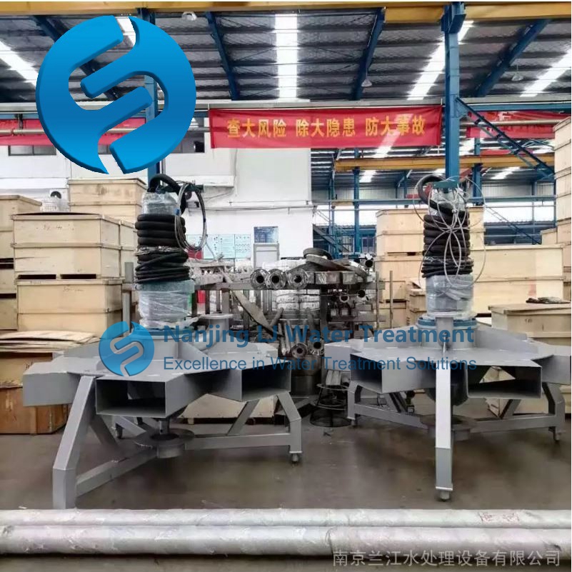
Baseline coverage calculation based on effective tank area and depth
The starting point of quantity calculation is to map the hydrodynamic influence range of each unit against the total available tank surface area and effective water depth. Each aeration mixer generates a specific agitation and gas dispersion footprint that extends horizontally and vertically, and this footprint expands or contracts depending on how deep the water column is and how much resistance exists near the tank floor. Engineers first define the minimum coverage radius required to prevent sludge sedimentation at the furthest point between two adjacent units, then use that radius to derive the preliminary number of positions that can cover the entire tank floor without leaving unaddressed gaps.
Correction factors for organic load and air distribution constraints
After obtaining the preliminary layout number, the next step is to adjust the total count to match actual process and airflow conditions. Systems with high organic inlet loads or elevated ammonia nitrogen concentrations require more uniform oxygen distribution, which means the original spacing between units must be reduced slightly to maintain consistent mass transfer performance. The total available system airflow is also divided evenly across all planned deployment points, ensuring that each unit operates within its stable aeration range and no single point receives insufficient or excessive air volume that breaks the balance of the whole system.
Final position optimization for structural and hydraulic obstacles
The last stage of calculation adjusts the preliminary quantity to account for real-world tank structures that interfere with ideal uniform arrangement. Internal baffles, support columns, inlet and outlet weirs, and sludge return points all create local flow shadows that cannot be fully covered by standard evenly spaced layouts. Engineers add extra positions near these low-circulation zones and remove redundant units from areas where flow from adjacent mixers already provides sufficient coverage, resulting in a final batch deployment count that balances theoretical calculation with actual site operating conditions.
Post time:2026-09-18
